Summary
Gnuman requires 3 position
encoders and 3 velocity encoders. The
velocity encoders are already on the robot and use incremental encoders. As for the position encoders that require an
absolute position (independent of power cycles), Incremental encoders with a
home/zero position make the most sense.
While Synchros, Resolvers, and Absolute encoders would suffice, the cost
can be as much as 7-8 times more expensive.
The benefits of having a Resolver/Synchro able to operate in extreme
conditions, be more durable, and more accurate are offset by the price. Likewise, while Absolute encoders provide
digital position data which can be processed more easily, the cost makes it
impractical.
Position control for motors (Rotary Encoders)
A rotary encoder is an electromechanical switch used to measure angular position and angular motion. Its output is generally composed of a digital encoding of relative or absolute position. Specialized rotary encoders called synchros actually output into sinusoidal waves where the phase difference represents the angular position.
Synchros
Synchros
A Synchro is a generic term for a family of
transducing elements. These transducing
elements can be arranged in various ways to measure angular position. The synchro works on the rotating transformer
principle to generate secondary currents from a primary sinusoidal current.
The rotor is an extension of the shaft. Three windings are attached 120 degrees apart
and are connected to the terminals S1, S2, and S3. This type of connection is known as a wye connection. The
windings from the rotor are connected by slip rings and brushes to the
terminals R1 and R2.
An AC voltage, known as the reference voltage (usually
either 60Hz or 400Hz), is sent through the rotor winding and subsequent
voltages are induced in the stator windings proportional to the cos angle (f) between the rotor coil and stator coil. .The voltage induced across any pair of
stator terminals will be the sum or difference, depending on the phase, of the
voltages across the two coils concerned..
Reference voltage: A Sin wt
The voltages which will appear across the stator
terminals will be:
S1 to S3 = A sin wt Sin f
S3 to S2 = A sin wt Sin (f + 1200)
S2 to S1 = A sin wt Sin (f + 2400)
where f is the synchro shaft angle.
Resolvers
The Resolver is a type of synchro, sometimes called
Synchro Resolvers, in which the windings on the stator and rotor are at 90
degrees to each other instead of 120 degrees
as in the case of the general synchro. This allows the Resolver to take advantage of
the sinusoidal relationship between output voltage and shaft angle. Resolvers come in many forms with a wide
variety of winding configurations and transformation ratios. The simplest
Resolver would have a rotor with a single winding and a stator with 2 windings
at 90 degrees to each other.
AC reference voltage: A Sin wt
Then the voltages appearing on the stator terminals
will be:
S1 to S3 = V Sin wt Sin f
and S4 to S2 = V Sin wt Cos f
where f is the Resolver shaft angle.
Optical Encoders
Incremental
encoders
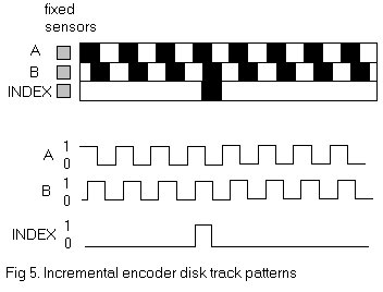
Incremental encoders consist of a disc, light source,
and light detector. The disc is made up
of evenly divided alternating light and dark sectors (ranging from opaque to
transparent) and is attached to the shaft.
The light source is placed on one side of the disc while the light
detector is on the other side. As the
disc turns (upon given rotation from a motor), the detector will detect on or
off depending on which part of the disc is in between the light source and
detector. From this, a square wave pulse
stream is produced. The sum of the
pulses is used to indicate angular position of the shaft and velocity
information can also be extracted based on the resolution. The resolution of the encoder is related to the
number of sectors the disc is divided into.
.The resolution of the encoder is governed by the number of opaque and
transparent sectors and usually falls between 100 and 6000 counts for one
complete revolution of the input shaft..
Almost all incremental encoders have a second light source and detector
which is phased correctly so that the direction of the
rotation can be obtained.
Also, many encoders even included a third light source
and detector which output only once per revolution making velocity measurements
attainable.
.Incremental encoders come in sizes ranging from 1
inch diameter (25.4 mm) to 3½ inches
diameter (88.9 mm). They are also available in all types of
external construction ranging from plastic, which is suitable for low cost
commercial applications, to stainless steel where the required specification is
more rigorous. While this type of encoder may be useful in some applications it
has the disadvantage of having the angular information stored in an external
counter. If the information in this counter is lost (for example if the power
supply was temporarily interrupted) there is no way of knowing the shaft angle.
Also at initial switch on, there is no way of determining the shaft angle until
it has been rotated through the revolution
marker..
Absolute
encoders
Absolute encoders are very similar to incremental
encoders. Here, the disc is divided into
N alternating dark and light sectors pertaining to a count (based on the coding
scheme). Each count relates to the bit
representation of the absolute position.
For example, for a 6 bit resolution, there will be 6 counts, one for
each bit. Each bit/count has its own
light source and detector. A set of light
sources are arranged radially on one side of the disc
and corresponding detectors are positioned on the other side such that a
parallel word representing the input shaft angle can be obtained at any one of
the angular positions.
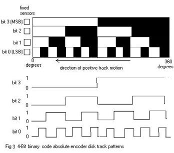
Therefore, the absolute position on the disc,
corresponding to the absolute position of the shaft, is always known. Even powering down does not affect the data. .Absolute optical encoders come with
resolutions of 6 to 16 bits in Gray code, binary or BCD and their sizes vary
from 2 inches (50.8 mm) to about 7 inches (177.8 mm) in diameter..
REFERENCES:
http://www.sensorwiki.org/index.php/Rotary_encoder
http://www.feedbackdevices.com/content.aspx?id=43
http://www.evaluationengineering.com/pctest/articles/0399daq.htm
http://amci.com/tutorials/tutorials-what-is-resolver.asp
http://www.analog.com/en/content/0,2886,760%255F%255F97528,00.html
http://en.wikipedia.org/wiki/Resolver_%28electrical%29
http://www.acalmicrosystems.co.uk/pdf/faq/synchrohandbook.pdf.
http://mechatronics.mech.northwestern.edu/design_ref/sensors/encoders.html