(renamed the "EIA232 Standard" in the early 1990's)
Written by Christopher E. Strangio
Copyright © 1993-1997 by CAMI Research Inc., Lexington, MassachusettsSend Us Your Comments . . . Contents
What is EIA232?
Likely Problems when Using an EIA232 Interface
Pin Assignments
Signal Definitions
Signal Ground and Shield
Primary Communications Channel
Secondary Communications Channel
Modem Status and Control Signals
Transmitter and Receiver Timing Signals
Channel Test Signals
Electrical Standards
Common Signal Ground
Signal Characteristics
Signal Timing
Accepted Simplifications of the Standard
Pin Description Index
References to EIA Publications
Back to CableEye Home Page
1 - The absence or misconnection of flow control (handshaking) signals, resulting in buffer overflow or communications lock-up.
2 - Incorrect communications function (DTE versus DCE) for the cable in use, resulting in the reversal of the Transmit and Receive data lines as well as one or more handshaking lines.
3 - Incorrect connector gender or pin configuration, preventing cable connectors from mating properly.
Fortunately, EIA232 driver circuitry is highly tolerant of
misconnections, and will usually survive a drive signal being
connected to ground, or two drive signals connected to each other.
In any case, if the serial interface between two devices is not
operating correctly, disconnect the cable joining this equipment
until the problem is isolated.
Go to DTE Pinout (looking into the computer's serial connector)
Go to DCE Pinout (looking into the modem's serial connector)
If the full EIA232 standard is implemented as defined, the equipment
at the far end of the connection is named the DTE device (Data
Terminal Equipment, usually a computer or terminal), has a male
DB25 connector, and utilizes 22 of the 25 available pins for signals
or ground. Equipment at the near end of the connection (the telephone
line interface) is named the DCE device (Data Circuit-terminating
Equipment, usually a modem), has a female DB25 connector, and
utilizes the same 22 available pins for signals and ground. The
cable linking DTE and DCE devices is a parallel straight-through
cable with no cross-overs or self-connects in the connector hoods.
If all devices exactly followed this standard, all cables would
be identical, and there would be no chance that an incorrectly
wired cable could be used. This drawing shows the orientation
and connector types for DTE and DCE devices:
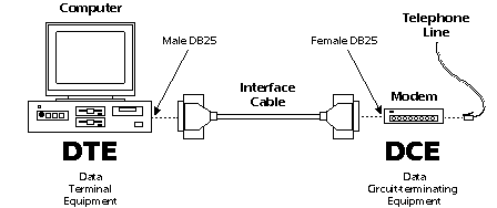
EIA232 communication function and connector types for a personal computer and modem. DCE devices are sometimes called "Data Communications Equipment" instead of Data Circuit-terminating Equipment.
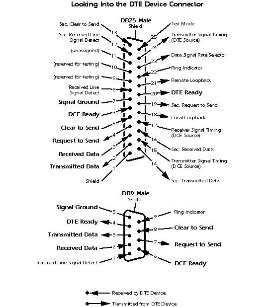
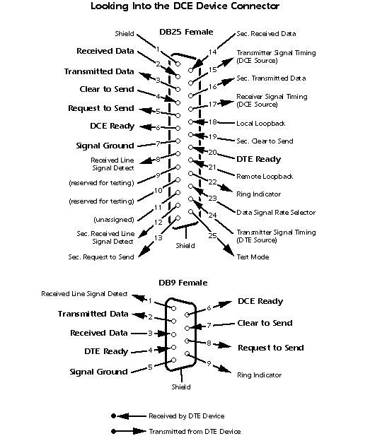
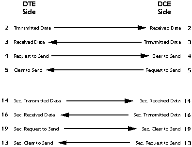
IMPORTANT: Signal names that imply a direction, such as Transmit Data and Receive Data, are named from the point of view of the DTE device. If the EIA232 standard were strictly followed, these signals would have the same name for the same pin number on the DCE side as well. Unfortunately, this is not done in practice by most engineers, probably because no one can keep straight which side is DTE and which is DCE. As a result, direction-sensitive signal names are changed at the DCE side to reflect their drive direction at DCE. The following list gives the conventional usage of signal names:
1 - Signal ground and shield.
2 - Primary communications channel. This is used for data interchange, and includes flow control signals.
3 - Secondary communications channel. When implemented, this is used for control of the remote modem, requests for retransmission when errors occur, and governance over the setup of the primary channel.
4 - Modem status and control signals. These signals indicate modem status and provide intermediate checkpoints as the telephone voice channel is established.
5 - Transmitter and receiver timing signals. If a synchronous protocol is used, these signals provide timing information for the transmitter and receiver, which may operate at different baud rates.
6 - Channel test signals. Before data is exchanged, the channel may be tested for its integrity, and the baud rate automatically adjusted to the maximum rate that the channel can support.
NOTE: Pin 2 on the DCE device is commonly labeled "Received Data", although by the EIA232 standard it should still be called Transmitted Data because the data is thought to be destined for a remote DTE device.
Pin 3 - Received Data (RxD)
This signal is active when the DTE device receives data from
the DCE device. When no data is transmitted, the signal is held
in the mark condition (logic '1', negative voltage).
NOTE: Pin 3 on the DCE device is commonly labeled "Transmitted Data", although by the EIA232 standard it should still be called Received Data because the data is thought to arrive from a remote DTE device.
Pin 4 - Request to Send (RTS)
This signal is asserted (logic '0', positive voltage) to
prepare the DCE device for accepting transmitted data from the
DTE device. Such preparation might include enabling the receive
circuits, or setting up the channel direction in half-duplex applications.
When the DCE is ready, it acknowledges by asserting Clear to Send.
NOTE: Pin 4 on the DCE device is commonly labeled "Clear to Send", although by the EIA232 standard it should still be called Request to Send because the request is thought to be destined for a remote DTE device.
Pin 5 - Clear to Send (CTS)
This signal is asserted (logic '0', positive voltage) by
the DCE device to inform the DTE device that transmission may
begin. RTS and CTS are commonly used as handshaking signals to
moderate the flow of data into the DCE device.
NOTE: Pin 5 on the DCE device is commonly labeled "Request to Send", although by the EIA232 standard it should still be called Clear to Send because the signal is thought to originate from a remote DTE device.
1 - The modem is connected to an active telephone line that is "off-hook";
2 - The modem is in data mode, not voice or dialing mode; and
3 - The modem has completed dialing or call setup functions and is generating an answer tone.
If the line goes "off-hook", a fault condition is detected,
or a voice connection is established, the DCE Ready signal is
deasserted (logic '1', negative voltage).
IMPORTANT: If DCE Ready originates from a device other than a modem, it may be asserted to indicate that the device is turned on and ready to function, or it may not be used at all. If unused, DCE Ready should be permanently asserted (logic '0', positive voltage) within the DCE device or by use of a self-connect jumper in the cable. Alternatively, the DTE device may be programmed to ignore this signal.
Pin 20 - DTE Ready (DTR)
This signal is asserted (logic '0', positive voltage) by
the DTE device when it wishes to open a communications channel.
If the DCE device is a modem, the assertion of DTE Ready prepares
the modem to be connected to the telephone circuit, and, once
connected, maintains the connection. When DTE Ready is deasserted
(logic '1', negative voltage), the modem is switched to "on-hook"
to terminate the connection.
IMPORTANT: If the DCE device is not a modem, it may require DTE Ready to be asserted before the device can be used, or it may ignore DTE Ready altogether. If the DCE device (for example, a printer) is not responding, confirm that DTE Ready is asserted before you search for other explanations.
Pin 8 - Received Line Signal Detector
(CD) (also called carrier detect) This signal is
relevant when the DCE device is a modem. It is asserted (logic
'0', positive voltage) by the modem when the telephone line is
"off-hook", a connection has been established, and an
answer tone is being received from the remote modem. The signal
is deasserted when no answer tone is being received, or when the
answer tone is of inadequate quality to meet the local modem's
requirements (perhaps due to a noisy channel).
Pin 12 - Secondary Received Line
Signal Detector (SCD) This signal is equivalent to
the Received Line Signal Detector (pin 8), but refers to the secondary
channel.
Pin 22 - Ring Indicator (RI)
This signal is relevant when the DCE device is a modem, and
is asserted (logic '0', positive voltage) when a ringing signal
is being received from the telephone line. The assertion time
of this signal will approximately equal the duration of the ring
signal, and it will be deasserted between rings or when no ringing
is present.
Pin 23 - Data Signal Rate Selector
This signal may originate either in the DTE or DCE devices
(but not both), and is used to select one of two prearranged baud
rates. The asserted condition (logic '0', positive voltage) selects
the higher baud rate.
NOTE: optical isolators may be used to achieve ground isolation, however, this option is not mentioned or included in the EIA232 specification.
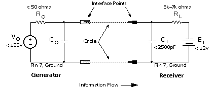
This is the equivalent circuit for an EIA232 signal line and applies to signals originating at either the DTE or DCE side of the connection. "Co" is not specified in the standard, but is assumed to be small and to consist of parasitic elements only. "Ro" and "Vo" are chosen so that the short-circuit current does not exceed 500ma. The cable length is not specified in the standard; acceptable operation is experienced with cables that are less than 25 feet in length.
Signal State Voltage Assignments - Voltages of -3v to -25v
with respect to signal ground (pin 7) are considered logic '1'
(the marking condition), whereas voltages of +3v to +25v are considered
logic '0' (the spacing condition). The range of voltages between
-3v and +3v is considered a transition region for which a signal
state is not assigned.
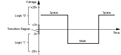
Logic states are assigned to the voltage ranges shown here. Note that this is a "negative logic" convention, which is the reverse of that used in most modern digital designs.
Most contemporary applications will show an open-circuit signal voltage of -8 to -14 volts for logic '1' (mark), and +8 to +14 volts for logic '0' (space). Voltage magnitudes will be slightly less when the generator and receiver are connected (when the DTE and DCE devices are connected with a cable).
IMPORTANT: If you insert an LED signal tester in an EIA232 circuit to view signal states, the signal voltage may drop in magnitude to very near the minimum values of ­p;3v for logic '1', and +3v for logic '0'. Also note that some inexpensive EIA232 peripherals are powered directly from the signal lines to avoid using a power supply of their own. Although this usually works without problems, keep the cable short, and be aware that noise immunity will be reduced.
Short-Circuit Tolerance - The generator is designed to
withstand an open-circuit (unconnected) condition, or short-circuit
condition between its signal conductor and any other signal conductor,
including ground, without sustaining damage to itself or causing
damage to any associated circuitry. The receiver is also designed
to accept any signal voltage within the range of ±25 volts
without sustaining damage.
CAUTION: Inductive loads or magnetically induced voltages resulting from long cables may cause the received voltage to exceed the ±25-volt range momentarily during turn-on transients or other abnormal conditions, possibly causing damage to the generator, receiver, or both. Keep the cable length as short as possible, and avoid running the cable near high-current switching loads like electric motors or relays.
Fail-Safe Signals - Four signals are intended to be fail-safe
in that during power-off or cable-disconnected conditions, they
default to logic '1' (negative voltage). They are:
Request to Send - Default condition is deasserted.
Sec. Request to Send - Default condition is deasserted.
DTE Ready - Default condition is DTE not ready.
DCE Ready - Default condition is DCE not ready.
Note specifically that if the cable is connected but the power
is off in the generator side, or if the cable is disconnected,
there should be adequate bias voltage in the receiver to keep
the signal above +3v (logic '0') to ensure that the fail-safe
requirement is met.
Schmitt triggers or other hysteresis devices may be used to enhance
noise immunity in some designs, but should never be adjusted to
compromise the fail-safe requirement.
1 - Signals that enter the transition region during a change of state must move through the transition region to the opposite signal state without reversing direction or reentering.
2 - For control signals, the transit time through the transition region should be less than 1ms.
3 - For Data and Timing signals, the transit time through the transition region should bea - less than 1ms for bit periods greater than 25ms,
b - 4% of the bit period for bit periods between 25ms and 125µs,
c - less than 5µs for bit periods less than 125µs.
The rise and fall times of data and timing signals ideally should be equal, but in any case vary by no more than a factor of three.An acceptable pulse (top) moves through the transition region quickly and without hesitation or reversal. Defective pulses (bottom) could cause data errors.
4 - The slope of the rising and falling edges of a transition should not exceed 30v/µS. Rates higher than this may induce crosstalk in adjacent conductors of a cable.
Note that neither the ASCII alphabet nor the asynchronous serial
protocol that defines the start bit, number of data bits, parity
bit, and stop bit, is part of the EIA232 specification. For your
reference, it is discussed in the Data
Communications Basics section of this web site.