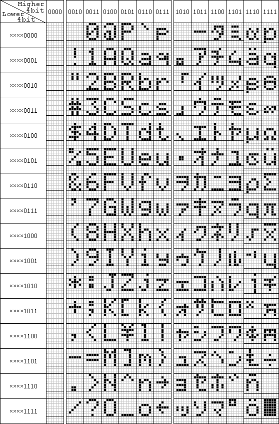

Each user-defined character is a 5X8 character in an 8X8 block. The mapping between the CG RAM locations and the displayed character is shown in the following figure. If the 5X10 dot display arrangement is used, only 4 user-defined characters are supported and the characters are defined with 11 bytes each.
        CG Address      CG Data
                        D7-----------D0
        x+0             . . . 1 1 1 1 1         *****
        x+1             . . . 1 0 0 0 0         *
        x+2             . . . 1 0 0 0 1         *   *
        x+3             . . . 1 1 1 1 1   =     *****
        x+4             . . . 1 0 0 0 1         *   *
        x+5             . . . 1 0 0 0 0         *
        x+6             . . . 1 0 0 0 0         *
        x+7             . . . 0 0 0 0 0         (cursor line)
As you can see in the above figure, each byte of CG RAM represents 1 row of pixels in the character, with D0 being the rightmost pixel, and D4 being the leftmost (the upper 3 bits are not displayed). The first address for a character is the topmost row, while the 7th is the bottom. (The 8th is ORed with the cursor underbar). A `1' in a pixel position becomes a dark pixel on the display. CG RAM occupies a separate address space from the data display (DD) RAM. One must set the (first) CG address before writing any CG data. Each write automatically increments/decrements the CG address pointer to the next location. Remember to set the display back to DD addressing mode before trying to write characters to be displayed.
As an example, we'll define character #3 to be the above symbol by writing the CG address to the start of the character's RAM then writing the successive rows of pixel data.
        RS R/W D7----D0
        0  0   01011000         Set CG RAM address to char #3
        1  0   00011111         Write top row of pixels
        1  0   00010000                 :
        1  0   00010001                 :
        1  0   00011111                 :
        1  0   00010001                 :
        1  0   00010000                 :
        1  0   00010000         Write bottom row of pixels
        1  0   00000000         Write cursor row (descender)