Intelligent Machines Design Lab IMDL Home

Hacking the Radio Shack IR Detector

This was taken from another website, and we haven't yet tried it here in IMDL, so it is provided with NO GUARANTEES.
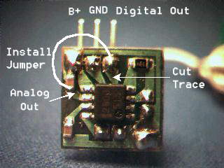
This shows how to modify an IR detector to provide analog signal output. This is useful for building IR distance sensors. The original hack was posted here. This modification is made on the Radio Shack IR Detector Module cat no. 276-137. It will also work on simular detectors sold for use with IR remote control units.

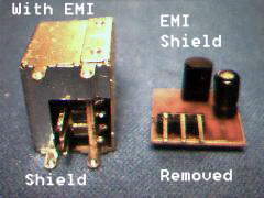
Some of these units come in Metal EMI shields. Remove the shield by unsnapping the cover . The snaps are on the top right side and can be seen in the photo to the left. After the EMI shield is removed you are left with a small PCB. The side shown has the IR photodetector and a capacitor on the side with the terminals. Flip the board over to the circuit side. There you will find a surface mount IC and three other components.
The second photo shows where the various signals are availabe on the board. If you want to maintain the digital signal just solder a fine wire to the analog signal pin. If you only plan on using it for analog measurements use a razor knife to cut the indicated trace and solder in a jumper as shown. You can even put it back in the metal EMI shield if you want.

The analog voltage varies from about 1.6v to 2.2v depending on how strong the IR signal is. To test this build a circuit to drive an IR LED at 38-40khz depending on the particular model of IR detector you have. Hook up the modified detector to a 5V power source and a volt meter to the analog output. Shine the LED at a wall. Move the detector closer and farther away from the wall. You should see the volt meter change as you move the sensor closer and farther away. To get the best results its a good idea to use an op amp to amplify the signal so it covers the range of your A-to-D converter.


This page maintained by Aamir Qaiyumi