Subjugator Generation 1: Background
|
An autonomous underwater vehicle competition was being put
together by the
Association for Unmanned Vehicle Systems International
which was to be held in August of 1996. After
hearing about the competition, a small interdisciplinary group of
university students consisting of mechanical and electrical engineers
got together to design and build a submarine.
 Since the rules didn't exist until the end of December, a lot
needed to happen in order to make it in the eight-month deadline.
A proposal was written at the end of January to acquire funds for
the building of the submarine.
Since the rules didn't exist until the end of December, a lot
needed to happen in order to make it in the eight-month deadline.
A proposal was written at the end of January to acquire funds for
the building of the submarine.
The group of students got together to discuss the body shape, the
control, and layout of the components. After about two months of
deliberation on the motor layout, and the consideration of
various body shapes and materials (a pony keg was considered at
one point, hmmm students and beer, go figure), it was decided to
go with something simple (always a good choice).
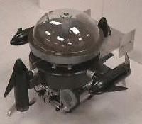
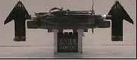
Four motors were chosen to drive the sub, and they were
positioned so that each pair was orthogonal. The fore and aft
motors were positioned downward to provide vertical motion (z-
translation) and pitch stability. The port and starboard motors
were positioned horizontally to provide forward/backward motion
(x-translation) when the props rotated in the same direction and
rotation (z-rotation) when they were spun at different RPMs. The
body was a simple cylindrical shape for easy of construction, and
reduction of drag.
|
Body
|
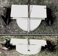
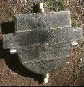
With only six months, we set about cutting out the body from the
foam, acquiring the hardware, and building the electronics. For
strength, the motors were attached to the body through steel
tubing.
The volume require to float the various components was
calculated, and the body was cut to rough size. Once the pieces
were in place, the body was smoothed out, and the glass material
was laid on top.
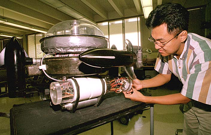
Two clear 10.16 cm acrylic tubes were added to house the various electronics
(clear, so that we could see when something went wrong (not that it ever
did, oh no...). One of the tube endcaps was made from aluminum to serve
as a heat sink for the motor drivers.
|
For roll stability, the weight (mostly the battery) of the sub
was placed low, while the buoyancy was placed higher up. This
allowed the sub to maintain roll (and some pitch) stability due
to the moments created by these two forces.
|
Power and Propulsion
|
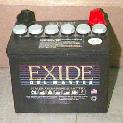 An Exide 12V Gel cell battery supplies power for the motors. A separate
power supply, housed within the acrylic tube, is used for the electronics.
The electronics are optically isolated to minimize coupling between the
electronics and the electrical noise from the motors.
An Exide 12V Gel cell battery supplies power for the motors. A separate
power supply, housed within the acrylic tube, is used for the electronics.
The electronics are optically isolated to minimize coupling between the
electronics and the electrical noise from the motors.
|
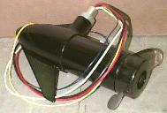 Four Minn Cota motors are used for propulsion. Each motor provides 24
pounds of thrust. Two are fixed vertically, fore and aft, and provide
pitch stability and ascent/decent thrust. The other two are fixed
horizontally, port and starboard, and provide forward/backward thrust,
and turning thrust.
Four Minn Cota motors are used for propulsion. Each motor provides 24
pounds of thrust. Two are fixed vertically, fore and aft, and provide
pitch stability and ascent/decent thrust. The other two are fixed
horizontally, port and starboard, and provide forward/backward thrust,
and turning thrust.
|
Mechanics
|
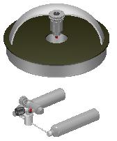
Since the competition called for picking up an object, we worked
on a buoyancy control system consisting of air tanks, a buoyancy
compensator and an air valve. The initial buoyancy compensator
was a large flower pot. It later progressed into a clear 17 inch
salad bowl. The two spare air tanks ran into a regulator to drop
the pressure. This regulated pressure was split, one half ran through
a solenoid to an air actuated valve to fill the compensator with water,
the other ran through a solenoid to fill the compensator with air.
|
Electronics and Sensors
|
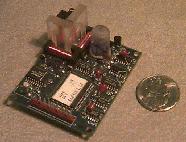
H-bridge Motor Driver
The original H-bridge motor drivers were from Motorola. They proved to be
a little on the sensitive, and hard to come by since Motorola stopped
manufacturing them.
From there, a new motor driver was designed and built using discrete
components.. [more detail here]
|
Digital Compass
The
Precision Navigation TCM2 digital compass is a high-performance,
low-power electronic compass sensor that outputs compass heading, pitch,
and roll readings via electronic interface to a host system. It is based
upon a proprietary triaxial magnetometer system and a biaxial electrolytic
inclinometer, and contains no moving parts.
|

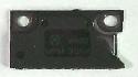
Pressure Sensor
The Omega PX180
pressure sensor measures 0-30 PSIG in millivolt range. The silicon
sensor is bonded on a glass pedestal to isolate it from induced stresses,
provides wide media compatibility, and the stainless steel pressure port
permits use with corrosive substances.
|
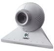
Digital Camera
The Connectix color Quickcam (now logitech) is
capable of up to 24 frames per second or a 320 x 240 image. The parallel
port connection makes it possible to connect this piece of hardware to
any board with a parallel port (that, and some good bit of coding).
|
Low-level Control
|
A motorolla 68HC11 was chosen to interface to all of the sensors and
to drive the motors. The code was written in assembly language.
Originally, input from a R/C joystick was translated into sub movements.
The user had total control of the horizontal thrust motors, and the
solenoids for the buoyancy control. The user could "dial-in" a depth
from the joystick, and the sub would seek that depth. This added in
shaking out some problems in controlling the sub autonomously.
The commands from the joystick to the motors were converted to
a direction and a Pulse Width Modulated (PWM) signal. Pitch data from
the compass was integrated to stabilize the sub as it moved around.
Depth was calculated from the pressure sensor and compared to the desired
depth.
|
High-level Software
|
To complete the transition to a fully autonomous sub, the original
68HC11 was replaced with one which had 32K of RAM so that the code
could be written in C.
On startup, the submarine would turn the z-axis motors on to drive
the sub down while opening the air-valve to fill the buoyancy compensator.
This would get the sub neutrally buoyant. Form there, it would dive to
the desired depth and maintain that depth while trying to travel a
constant heading taken from the compass.
The color camera would then be used to find and navigate toward the
gates. The camera image would be analyzied to find the outline of the
gate, and then the sub would drive torward the centroid.
|
